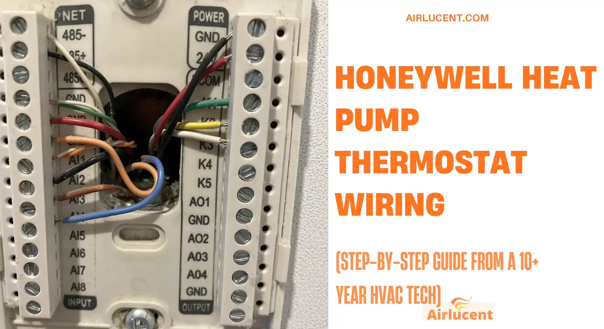
Hi, I’m Nathan. I’ve worked as an HVAC technician for over 10 years, and one of the most common “simple but stressful” jobs I see homeowners deal with is wiring a Honeywell thermostat to a heat pump.
Heat pump thermostat wiring is not hard once you understand two things:
- Heat pumps use a reversing valve (O or B)
- Many heat pumps also use Auxiliary and Emergency heat (Aux and E)
In this guide, I’ll walk you through exactly how I wire Honeywell heat pump thermostats in the field, how to identify your system, which terminals to use, and how to avoid the few mistakes that cause the biggest headaches.
Quick safety note (read this first)
Even though thermostats are typically 24VAC low voltage, you can still:
- Blow a fuse on the air handler control board
- Short the transformer
- Cause the system to run heat strips nonstop (expensive)
Turn off power at the breaker to both the air handler and the outdoor unit before touching thermostat wires.
If you’re ever unsure, stop and call a licensed HVAC tech. One service call is cheaper than a fried board.
What you’ll need
Here’s what I keep on hand for a clean install:
- Honeywell thermostat compatible with heat pumps (most “Pro” and many “Home” models are, but always verify)
- Small flathead and Phillips screwdriver
- Wire strippers
- Needle-nose pliers (optional but helpful)
- Drill and anchors (if the wall is soft or holes don’t line up)
- Level (optional, but it keeps it looking professional)
- Phone camera (seriously, your best tool)
- Voltage tester or multimeter (recommended)
Heat pump wiring
A heat pump is an air conditioner that can run in reverse. That “reverse” is controlled by the reversing valve wire:
- O (often orange): reversing valve energized in cooling on many brands
- B (sometimes blue): reversing valve energized in heating on some systems
Then you may have backup heat, usually electric heat strips or a furnace (dual fuel). That backup heat is controlled by:
- Aux/W1 for auxiliary heat (automatic assist)
- E for emergency heat (manual, when the heat pump is locked out)
Heat pump thermostat wire colors and terminals (cheat sheet)
Wire colors are common, but not guaranteed. I always tell homeowners: trust the terminal letters, not the color.
Honeywell heat pump wiring color code table
| Red | R, Rc, Rh | 24V power from transformer |
| Blue or Black | C | Common (needed for many smart thermostats) |
| Yellow | Y or Y1 | Compressor stage 1 |
| Light Blue or another color | Y2 | Compressor stage 2 (if you have 2-stage) |
| Green | G | Indoor fan relay |
| Orange | O/B | Reversing valve (O or B setup depends on system) |
| White | Aux/W1 | Auxiliary heat (heat strips or backup heat stage) |
| Brown (varies) | E | Emergency heat (sometimes separate, often not used) |
| Pink/Black (varies) | L | Heat pump fault signal (not always present) |
| Two wires (varies) | S, S1/S2 | Outdoor sensor (some Honeywell setups) |
| K (special) | K | Honeywell saver module connection (varies by model) |
Before you disconnect anything (this saves people every time)
When I replace a thermostat, I do this exact routine:
- Kill power at the breaker
- Remove the thermostat faceplate
- Take a clear photo of the old wiring (close-up, in focus)
- Label wires by terminal letter if labels aren’t already there
- Gently pull wires out so you have slack
- Wrap a little tape around the wire bundle so it can’t fall into the wall
That photo alone can prevent 90 percent of wiring mistakes.
Step-by-step: How to wire a Honeywell thermostat to a heat pump

1) Turn off the power
Turn off breakers for:
- Air handler/furnace
- Outdoor condenser/heat pump (if it’s on a separate breaker)
2) Remove the old thermostat (don’t disconnect yet)
Take your photo and confirm which terminals are used.
3) Mount the Honeywell wall plate
- Feed wires through the opening
- Level it
- Screw it down snug (not crushing drywall)
4) Connect wires to matching terminals
Match each wire to the same letter terminal.
Typical heat pump core connections are:
- R to R (or Rc/Rh depending on model)
- C to C (if present)
- Y to Y (compressor)
- G to G (fan)
- O/B to O/B (reversing valve)
- Aux/W1 to Aux (if you have backup heat strips or dual fuel control)
5) Set the thermostat up for “Heat Pump”
This is where a lot of installs go wrong. Wiring can be correct but configuration wrong.
During setup, you’ll select things like:
- Heat pump type (1 stage vs 2 stage)
- Aux heat present (yes/no)
- Reversing valve setting (O or B)
6) Restore power and test modes
Test in this order:
- Fan only (does indoor fan run?)
- Cooling (does outdoor unit run and blow cool?)
- Heating (does outdoor unit run and blow warm?)
- Aux heat (if applicable)
The most common Honeywell heat pump wiring setups (with tables)

Below are the common real-world wiring combinations I see most often.
Setup A: 1H/1C Heat Pump (no Aux heat) typically 5 to 6 wires
This is a basic heat pump with no electric heat strips connected to the thermostat.
| R | R (red) | 24V power |
| C (optional) | C (blue/black) | Common |
| Y | Y (yellow) | Compressor |
| G | G (green) | Fan |
| O/B | O or B (often orange) | Reversing valve |
Important note from the field: Many Honeywell manuals warn not to use W for heat pump applications unless it’s specifically labeled as Aux/W1 and you actually have auxiliary heat.
Setup B: 1H/1C Heat Pump with Aux or Emergency heat typically 6 to 8 wires
This is extremely common on all-electric homes: heat pump plus electric heat strips.
| R | R | 24V power |
| C | C | Common |
| Y | Y | Compressor stage 1 |
| G | G | Fan |
| O/B | O/B | Reversing valve |
| Aux/W1 | Aux (often white) | Heat strips (automatic) |
| E (sometimes) | E (varies) | Emergency heat (manual, sometimes not used) |
| L (optional) | L (varies) | Fault indicator input |
Aux vs Emergency heat (how I explain it to homeowners)
- Aux heat comes on automatically when it’s too cold outside or the system can’t keep up.
- Emergency heat is something you turn on manually when the outdoor heat pump is not working or you want it locked out.
In many systems, Aux and E energize the same heat strips, so you may not have a separate E wire.
Setup C: 2-stage heat pump (2 compressors or 2 stages) typically 7 to 9 wires
If you have two-stage compressor operation, you’ll usually have Y1 and Y2.
| R | R | 24V power |
| C | C | Common |
| Y1 | Y1 | Compressor stage 1 |
| Y2 | Y2 | Compressor stage 2 |
| G | G | Fan |
| O/B | O/B | Reversing valve |
| Aux/W1 (if present) | Aux/W1 | Backup heat strips or secondary heat |
| L (optional) | L | Fault |
Setup D: Dual fuel (heat pump + gas furnace) wiring overview
Dual fuel is where I recommend extra caution. Thermostat wiring might be simple, but the control logic and lockouts matter (outdoor temperature sensor, fossil fuel kit, equipment interface module, etc.).
In dual fuel setups, the thermostat may control:
- Heat pump stages (Y1/Y2, O/B)
- Furnace heat call (often W coming from furnace control)
- Outdoor sensor (S terminals on some Honeywell models)
If your Honeywell model supports dual fuel directly, follow its specific dual fuel diagram and configuration menu.
If you’re not 100 percent sure you have it configured correctly, this is a good point to call a pro. A miswired dual fuel system can run the furnace and heat pump in the wrong sequence.
R, Rc, Rh: Do you need a jumper?
This depends on your system and thermostat model.
If you have one R wire
- Many Honeywell thermostats internally bridge R to Rc, or they use a slider tab on Pro models.
- If your thermostat requires it, you’ll either use the built-in slider setting or a jumper.
If you have separate Rc and Rh wires
- Put each wire on its correct terminal if the thermostat supports both.
- Do not force them together unless the manual says to.
Practical tip: If you see two transformers (rare in modern heat pumps, more common on older systems), you must wire Rc and Rh correctly.

O vs B reversing valve: the setting that makes heat feel like cool
This is the classic symptom:
- You switch to heat
- The system blows cool air (or vice versa)
That often means the reversing valve is set wrong.
Quick rule
- If your old thermostat used O, set Honeywell to O
- If it used B, set it to B
Some heat pumps energize the reversing valve in cooling (O), others in heating (B). The wiring might be correct but the installer setup option is wrong.
C wire: Do you actually need it?
Many basic Honeywell thermostats can run without a C wire (battery powered). Many WiFi or smart models typically need C.
What the C wire does
C is the return path for 24V power. Without it, smart thermostats may:
- Randomly reboot
- Not maintain WiFi
- Short-cycle equipment
Your options if you don’t have a C wire
- Use an existing unused wire in the wall bundle (best case)
- Run a new thermostat cable (best long-term)
- Use a Honeywell saver module (K terminal on supported models)
- Use an add-a-wire kit compatible with your system
Honeywell K wire (what it is in real installs)
On some Honeywell setups, K is used for a “wire saver” style module so the thermostat can get a common connection even if your wall cable is short on conductors.
In plain terms: it’s a workaround when the thermostat needs more wiring than your cable provides.
Important: Only use K if your thermostat supports it and you’re following that exact Honeywell diagram. Don’t guess with K.
Common mistakes I see (and how to avoid them)
Mistake 1: Connecting a heat pump to W like a furnace
On many Honeywell heat pump diagrams: do not use W unless it’s specifically configured as Aux/W1 for auxiliary heat.
If W is misused, you can end up with:
- Heat strips running constantly
- High electric bills
- Poor comfort
Mistake 2: Skipping installer setup
Wiring is only half the job. Heat pump thermostats must be configured for:
- Heat pump type
- Number of stages
- Aux heat present
- O/B setting
Mistake 3: Assuming wire colors are “standard”
I’ve opened walls where:
- Yellow was on W
- White was on Y
- Blue was on O
Always follow terminal letters, not color.
Troubleshooting table (fast fixes)
| Thermostat won’t turn on | No power, blown low-voltage fuse, no C (smart stat) | Breakers, air handler fuse, R to C voltage |
| Cooling works but heating doesn’t | O/B misconfigured, Aux not wired/configured | Verify O vs B setting, check Aux/W1 |
| Heat runs but air feels cool | Reversing valve wrong or defrost cycle | Check O/B setting, allow time, check outdoor unit |
| Fan doesn’t run | G wire not connected or fan controlled by equipment | Check G terminal connection and system settings |
| Aux heat never comes on | Aux not wired or thermostat not configured | Confirm Aux/W1 wire, installer setup |
| Aux heat always on | Wire on wrong terminal, stuck relay, wrong setup | Confirm Aux/W1 wiring, check staging settings |
| Outdoor unit runs in EM Heat mode | Wired/configured wrong | Emergency heat should typically lock out compressor |
Useful real-world stats (why correct wiring matters)
- The U.S. Department of Energy notes that high-efficiency heat pumps can reduce electricity use for heating by about 50 percent compared with electric resistance heating in many situations. That only happens if staging and Aux heat are wired and configured correctly.
- The DOE also commonly cites that adjusting temperature setbacks (like using programmable scheduling properly) can save up to about 10 percent per year on heating and cooling costs.
If Aux heat is running when it shouldn’t, those savings disappear fast.
FAQs: Honeywell heat pump thermostat wiring
Can I use any Honeywell thermostat with a heat pump?
No. You need a model that supports heat pump control and ideally auxiliary heat if your system has it. Check the box or spec sheet for “heat pump compatible” and the number of heat/cool stages.
How do I know if I have Aux heat?
Common clues:
You see an Aux/W1 wire on the old thermostat
Your air handler has electric heat strips
Your thermostat screen sometimes shows “Aux Heat” in cold weather
What if I only have 2 or 3 wires?
That usually isn’t a typical heat pump thermostat setup. Some systems use equipment interface modules or different control strategies. I’d want to see your existing wiring photo before recommending anything.
Should I shut off power even though it’s low voltage?
Yes. I’ve replaced plenty of 3A or 5A fuses on air handlers because someone let R touch C or metal.
What if the system turns on but acts weird?
Most of the time, it’s not the wiring, it’s the installer setup (heat pump type, O/B, staging, Aux heat settings).
My closing advice (from the field)
If you take nothing else from this guide, remember my “3-photo rule”:
- Photo of old thermostat wiring
- Photo of the wires after you remove the old thermostat (labels visible)
- Photo of the new Honeywell terminals once everything is landed