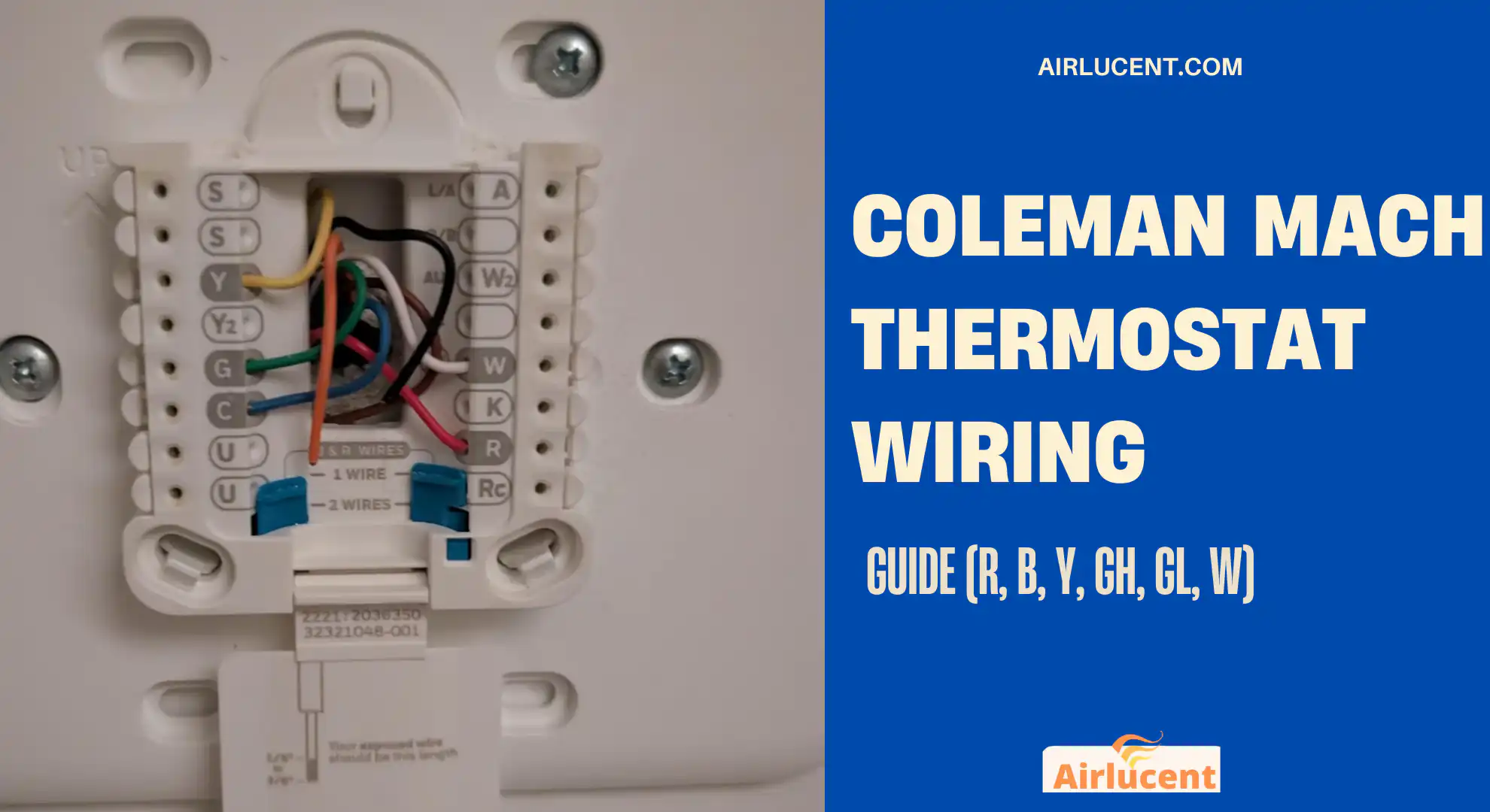
If you’re wiring or replacing a Coleman Mach RV thermostat, here’s the most important thing I want you to know before you touch a single wire:
Coleman Mach thermostats are 12V DC control systems (from your RV batteries and converter), not 24V AC like a house thermostat.
I’ve seen a lot of good DIYers get tripped up because the terminal letters look familiar, then they wire it like residential HVAC and nothing works (or a fuse pops instantly). In this guide, I’ll walk you through the correct terminal meanings, wire mapping, safe replacement steps, and the exact multimeter checks I use when a fan, compressor, or furnace won’t respond.
- Safety first (please do not skip this)
- Quick answer (what wires go where)
- Coleman Mach thermostat terminals explained (with typical colors)
- The biggest confusion: GH and GL (why there are two fan wires)
- Which Coleman Mach thermostat do you have?
- Real-world RV voltage numbers (so your meter readings make sense)
- Wire colors can change at the ceiling plenum (this is normal)
- Tools I actually use for this job
- Step-by-step: replacing or rewiring a Coleman Mach thermostat
- Multimeter troubleshooting (my go-to checks)
- Common wiring scenarios (including the “two bundles of wires” situation)
- Mistakes I see most (so you don’t repeat them)
- When to stop and call a pro
- FAQ
- Is a Coleman Mach thermostat 12V or 24V?
- What do GH and GL mean on a Coleman thermostat?
- Is B the same as C (common) on a house thermostat?
- Why did everything stop working right after I rewired it?
- Are older Coleman Mach thermostats interchangeable?
- My wire colors don’t match any chart. What should I do?
- References I trust (and what I base this on)
Safety first (please do not skip this)
Even though the thermostat wiring is low-voltage 12V DC, the rooftop AC it controls switches 115V AC for the compressor and fan motors.
Before you remove the thermostat or open the ceiling plenum/control box:
- Turn the RV air conditioner breaker off.
- Unplug shore power.
- Turn the generator OFF.
- Turn the inverter OFF (if equipped).
- Disconnect the positive cable from every coach battery (or use the battery disconnect if it truly isolates the battery bank).
- Confirm the thermostat display is dark (no screen, no LEDs).
If you’re not 100 percent sure power is dead, stop and verify. A 12V short can blow fuses and damage boards. A 115V mistake can hurt you.
Quick answer (what wires go where)
Most Coleman Mach wall thermostats use these core terminals:
- R = +12V DC supply
- B = 12V DC ground (negative return)
- Y = compressor call (cooling)
- GH = high fan
- GL = low fan
- W = furnace heat call (usually propane furnace)
Some newer digital models add:
- WHP = electric heat / heat strip / heat pump strip heat (model dependent)
- SENS = remote temperature sensor input
Coleman Mach thermostat terminals explained (with typical colors)

Wire colors are common, but not guaranteed. I want you to wire by terminal letter first, color second.
Coleman Mach terminal chart
| R | Red | +12V DC feed from RV battery/converter |
| B | Blue | DC ground (negative return) |
| Y | Yellow | Sends +12V to compressor relay (cooling call) |
| GH | Green | Sends +12V to high fan relay |
| GL | Gray | Sends +12V to low fan relay |
| W | White | Sends +12V to furnace call (gas heat) |
| WHP (digital only) | White/black (often) | Sends +12V for electric heat strip or heat pump strip (varies by system) |
| SENS (digital only) | Varies / none | Remote temperature sensor input |
Important: There is no residential “C” here
On a house thermostat, C is a 24V AC common. On Coleman Mach, B is DC ground. They are not interchangeable. If you try to adapt a residential thermostat to this system, you’re in the wrong voltage and wrong control style.
The biggest confusion: GH and GL (why there are two fan wires)

Residential thermostats typically have one fan terminal: G.
Coleman Mach splits the fan into two outputs:
- GH = fan high speed
- GL = fan low speed
So if your old thermostat didn’t have fan speed selection, you might still find both GH and GL in the wall, or you might only have one connected depending on how it was installed.
Practical tip from the field: If you connect the wrong fan speed wire (or leave it off), you’ll get “cooling but no airflow” symptoms, icing, or short cycling. Fan speed matters.
Which Coleman Mach thermostat do you have?
In RVs, I commonly see four “generations”:
1) Mechanical (bimetal coil, no display)
- Simple switches and a temperature coil
- Same core terminals: R, B, Y, GH, GL, W
2) Electronic (often with a small LED bar)
- Same core terminals: R, B, Y, GH, GL, W
3) Electronic with digital temperature display
- Still the same core terminals: R, B, Y, GH, GL, W
4) Newer digital wall thermostat (examples: 9420381 / 9420382)
- Uses the same core terminals
- Adds WHP and SENS
- Uses dip switches to configure what equipment you have (cool only, gas heat, electric heat, heat pump setups depending on model)
Real-world RV voltage numbers (so your meter readings make sense)
A lot of people expect “12V” to mean exactly 12.0 volts. In an RV, you’ll usually see something like this:
| Battery resting (no charge) | ~12.2 to 12.7 V DC |
| Converter charging | ~13.2 to 13.6 V DC (sometimes higher) |
| Bulk/boost charge (some converters) | ~14.0 to 14.4 V DC |
So when I say “12V,” I mean “RV 12V system voltage.” Anything in that general range is normal.
Wire colors can change at the ceiling plenum (this is normal)
Here’s something that surprises owners: the wire color at the thermostat may not match the wire color at the ceiling control box.
That’s not you going crazy. Some ceiling plenum/control assemblies are documented to change colors partway through the run, especially on the compressor circuit.
Example mapping seen in certain ceiling plenum series
| Y | Yellow | Black (on some units) | Compressor relay |
| GH | Green | Green | High fan relay |
| GL | Gray | Gray | Low fan relay |
| B | Blue | Blue | Ground |
| W | White | White | Furnace/heat relay |
What I do on service calls: I trust terminal letters and I verify with continuity testing if anything looks questionable.
Tools I actually use for this job
You don’t need a garage full of gear. This is what helps you avoid mistakes:
- Phone camera (take photos before you remove anything)
- Small flat screwdriver (for push-tab connectors or terminal screws)
- Wire labels or masking tape and marker
- Wire stripper (for small gauge thermostat wire)
- Multimeter (DC volts and continuity)
- Flashlight
Wire gauge note: Many Coleman digital thermostats want around 20 AWG solid conductors at the connector. If your wire is stranded or a different size, you may need to tidy the end carefully so it seats securely.
Step-by-step: replacing or rewiring a Coleman Mach thermostat

Step 1: Kill power completely
Do all the shutoffs listed in the safety section. Confirm the thermostat is dark.
Step 2: Photograph the wiring
Take a clear, close photo of the old thermostat with all wires visible.
Step 3: Label wires by terminal letter (not just color)
This is huge. Label them R, B, Y, GH, GL, W (and WHP/SENS if present).
Step 4: Remove the old thermostat
Loosen terminal screws or release push connectors.
Step 5: Connect wires to the new thermostat by matching letters
- R to R
- B to B
- Y to Y
- GH to GH
- GL to GL
- W to W
For digital push-in connectors: strip the wire to the length specified by the thermostat (commonly about 5/16 inch), push until fully seated, then gently tug to confirm it’s locked.
Step 6: Set dip switches (digital thermostats)
Configure it for your setup. Common modes include:
- Cool only (no heat outputs)
- Gas heat (furnace on W)
- Electric heat (heat strip / accessory)
- Mixed modes (varies by thermostat and rooftop unit)
If you’re unsure, look up your rooftop unit model and thermostat model together. Coleman/Airxcel documentation is the deciding factor, not guesswork.
Step 7: Restore power and test in order
I test like this:
- Fan low
- Fan high
- Cooling (low fan, then high fan)
- Heat (furnace)
This sequence makes it easier to isolate problems.
Multimeter troubleshooting (my go-to checks)
These checks are done with the RV powered back on and the thermostat calling for the function.
What to measure (DC volts)
| Fan high | GH to B | 12 to 14.4 V DC | Thermostat is energizing high fan |
| Fan low | GL to B | 12 to 14.4 V DC | Thermostat is energizing low fan |
| Cooling call | Y to B | 12 to 14.4 V DC | Thermostat is energizing compressor relay |
| Heat call (gas furnace) | W to B | 12 to 14.4 V DC | Thermostat is calling for furnace |
If you read 0V on an output
Work backwards like I do in the field:
- Check R to B first.
If you do not have ~12V there, the thermostat isn’t being powered (blown fuse, open feed, battery disconnect, etc.). - If R to B is good, then check the output terminal (Y, GH, GL, W) to B while calling for that function.
If it stays at 0V, the thermostat isn’t sending power out (internal fuse, misconfiguration, failed thermostat).
The thermostat fuse problem (very common after rewiring)
Many Coleman electronic/digital stats have a small internal fuse (commonly 2 amp, sometimes a self-resetting style depending on model).
If everything was working, you rewired, and now nothing responds, I immediately suspect:
- A short during wiring
- A crossed R and B moment
- A pinched wire
- Blown thermostat fuse
This is one of the first things I check before condemning a relay board.
Common wiring scenarios (including the “two bundles of wires” situation)
You mentioned (and I see this a lot in RVs) two separate bundles coming into the thermostat opening. That’s normal. One bundle may go to the rooftop unit control box, and another may go to the furnace, depending on how the RV was built.
Typical Coleman Mach 6-wire function list (color-based, when standard)
This is the standard mapping many owners identify:
| Red | R (+12V DC) |
| Blue | B (DC ground) |
| Yellow | Y (compressor) |
| Green | GH (high fan) |
| Gray | GL (low fan) |
| White | W (heat/furnace) |
If one bundle only has red and white, that often ends up being:
- Red = +12V feed or furnace feed (depends on coach wiring)
- White = heat call to furnace
But do not assume. Label what was on the old thermostat terminals if possible. If the old thermostat is already removed and you’re unsure, use continuity testing to trace where each conductor goes.
Mistakes I see most (so you don’t repeat them)
1) Installing a residential 24V thermostat
It will not control your Coleman Mach correctly without additional interface equipment, and you can damage components. Coleman Mach is 12V DC logic.
2) Wiring by color only
Colors can change at the ceiling plenum. Always verify terminal letters and trace if needed.
3) Forgetting fan speed wiring
If GH and GL aren’t handled correctly, you can get no airflow, wrong airflow, freezing coils, or weak cooling.
4) Dip switch set wrong on digital thermostat
Cool Only mode disables heat. Some heat pump/electric heat options require WHP configured correctly.
5) Not fully killing power
I’ve watched owners pull a thermostat while the 12V system was still live and blow the small control fuse instantly.
When to stop and call a pro
I’m all for careful DIY, but I also know where jobs go sideways. Stop and get help if:
- You find 120V wiring (thicker wires, wire nuts, line-voltage controls) in the same area
- You’re not sure what is AC vs DC
- The rooftop control box needs replacement or you suspect a board failure
- You’re dealing with refrigerant or sealed system parts
- The furnace side involves anything past the control board (gas valve, ignition components)
Thermostat wiring is doable. Line voltage and gas safety circuits are a different category.
FAQ
Is a Coleman Mach thermostat 12V or 24V?
12V DC. It runs from the RV’s battery/converter system, not a 24V AC transformer.
What do GH and GL mean on a Coleman thermostat?
Fan High (GH) and Fan Low (GL). Coleman splits fan speed into two separate control outputs.
Is B the same as C (common) on a house thermostat?
No. B is DC ground on Coleman Mach. C is 24V AC common on residential systems.
Why did everything stop working right after I rewired it?
Most commonly: blown small fuse on the thermostat, shorted wire during install, or miswired R and B. Verify R to B voltage first, then check outputs.
Are older Coleman Mach thermostats interchangeable?
Many are interchangeable across the mechanical/electronic/digital-display styles because they share the same six core terminals. Newer digital models add WHP and SENS but still use the same core wiring.
My wire colors don’t match any chart. What should I do?
Go by terminal letter and verify with a multimeter. If needed, use continuity mode to trace wires end-to-end.
References I trust (and what I base this on)
- Coleman Mach / Airxcel / RV Products wall thermostat installation documentation (digital wall thermostat models such as the 9420381 / 9420382 family)
- Coleman Mach 12V DC wall thermostat service documentation for terminal functions and diagnostic logic
- My own field experience troubleshooting RV rooftop units, thermostat circuits, and furnace call wiring over 10 plus years as an HVAC technician