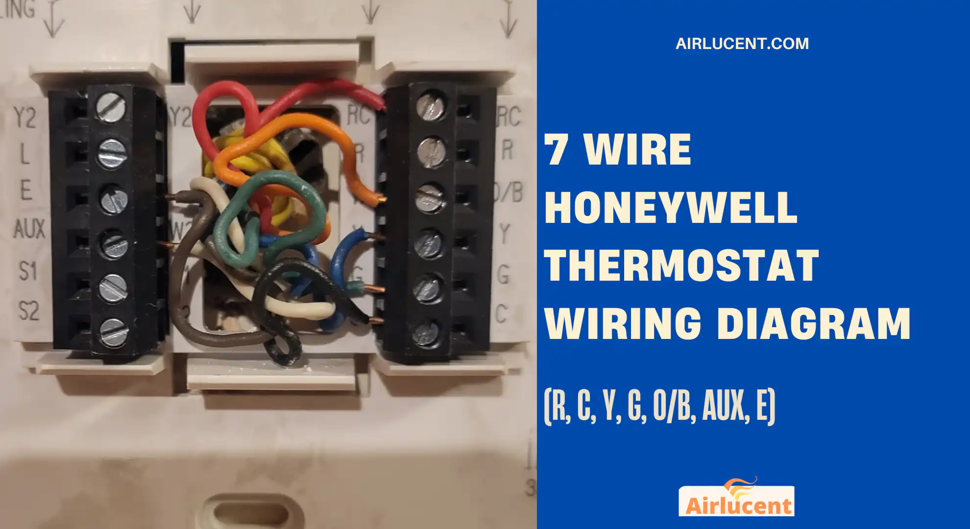
Hi, I’m Nathan. I’ve worked as an HVAC technician for over 10 years, and I’ve wired (and re-wired) more Honeywell thermostats than I can count. If you opened your thermostat and found 7 wires, you’re usually looking at a heat pump setup with both Auxiliary heat and Emergency heat, which is the most common reason Honeywell thermostats use R, C, Y, G, O/B, AUX, and E.
In this guide, I’ll walk you through:
- What each wire does (in plain English)
- A clean 7-wire Honeywell wiring diagram you can follow
- Color codes (and why you should not trust them blindly)
- How to tell if you have a heat pump or a conventional system
- Step-by-step wiring and setup tips that prevent the most common “it heats when I set cool” mistake
If you follow this carefully, you’ll wire it the same way I would on a service call.
- Quick answer: What 7 wires usually mean on a Honeywell thermostat
- 7-wire Honeywell thermostat wiring diagram (heat pump with AUX and E)
- The 7 terminals explained (one at a time, the way I explain it to homeowners)
- Typical Honeywell 7-wire color code (and what I see in real houses)
- Which 7-wire system do you actually have? (common configurations)
- Before you wire anything: the photo-and-label method I use
- Step-by-step: How to wire a 7-wire Honeywell thermostat (the clean way)
- Quick diagnostic: is your problem the thermostat or the equipment?
- Troubleshooting: common 7-wire Honeywell heat pump problems
- Brand tip: is your reversing valve “O” or “B”?
- FAQ
- My “know when to stop” checklist
Quick answer: What 7 wires usually mean on a Honeywell thermostat
In the field, when I see 7 wires on a Honeywell thermostat, it is most often:
- Heat pump (compressor)
- Reversing valve control (O/B)
- Fan control (G)
- Common wire (C) for constant power
- Aux heat (AUX) for automatic backup heat
- Emergency heat (E) for manual backup heat only
TL;DR wiring table
| R (or Rc/Rh) | Red | 24V power from transformer |
| C | Blue (sometimes black) | Common wire, completes 24V circuit |
| Y | Yellow | Compressor contactor (heat and cool on heat pumps) |
| G | Green | Indoor fan/blower relay |
| O/B | Orange (or dark blue) | Reversing valve (heat pump mode change) |
| AUX | White | Automatic backup heat (heat strips or fossil backup) |
| E | Brown | Emergency heat (manual backup, compressor locked out) |
My biggest rule: Match the terminal letters, not the wire colors.
Before disconnecting anything, take a close-up photo and label each wire by the terminal it was connected to.
7-wire Honeywell thermostat wiring diagram (heat pump with AUX and E)
Below is a simple diagram showing how the thermostat connects to the air handler control board for the common 7-wire heat pump setup.
Diagram: Thermostat to air handler control board
| R | R | 24V power |
| C | C | Common |
| Y | Y | Compressor |
| G | G | Fan |
| O/B | O or B (same terminal labeling varies) | Reversing valve |
| AUX | W2/AUX | Auxiliary heat |
| E | E (or sometimes W/E) | Emergency heat |
Simple “wire path” view
R thermostat to R air handler
C thermostat to C air handler
Y thermostat to Y air handler
G thermostat to G air handler
O/B thermostat to O/B air handler
AUX thermostat to AUX/W2 air handler
E thermostat to E air handler
If your air handler board doesn’t have an “E” terminal, don’t guess. Some systems combine emergency heat into W2/AUX internally, and the thermostat configuration changes.
The 7 terminals explained (one at a time, the way I explain it to homeowners)
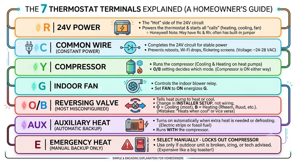
R: 24V power
R is the “hot” side of the 24V transformer. It powers the thermostat and is the starting point for most calls (cooling, heating, fan, etc.).
Honeywell note (important):
- Many Honeywell thermostats show Rc and Rh.
- If you only have one R wire, Honeywell often uses a built-in jumper or internal bridging so one transformer powers both.
C: Common wire (constant power)
C completes the 24V circuit so the thermostat has stable power.
From real service calls: missing or weak C wire is one of the top causes of:
- thermostat reboots
- Wi-Fi dropping
- screen flickering
- outdoor unit clicking but not starting
Typical voltage you’ll see:
- R to C: about 24 to 28 VAC under normal conditions
Y: Compressor (cooling and heating on a heat pump)
On a heat pump:
- Y energizes the compressor in both heating and cooling
- The reversing valve (O/B) decides whether the system is heating or cooling
This is why heat pumps can confuse people. The compressor is “on” either way.
G: Indoor fan
G controls the indoor blower relay.
- Fan set to ON at the thermostat usually means: thermostat energizes G.
- In heating mode, some systems control fan internally, but G is still the standard blower call terminal.
O/B: Reversing valve (the most-misconfigured setting)
This terminal makes it a heat pump.
Here’s the truth from the field: I see more bad O/B configuration than bad wiring.
- O means the reversing valve is energized in cooling (most brands)
- B means the reversing valve is energized in heating (commonly Rheem/Ruud and a few others)
You usually do NOT move the wire to change this.
You change it in the thermostat installer setup: choose O or B.
If this is set wrong, you’ll get:
- “It heats when I set it to cool”
- or “It cools when I set it to heat”
AUX: Auxiliary heat (automatic backup)
AUX is backup heat that comes on automatically when:
- it’s too cold outside for the heat pump to keep up
- the thermostat senses the house is falling behind the set temperature
- defrost cycles require supplemental heat
AUX is commonly:
- electric heat strips in the air handler
- or fossil fuel backup (dual fuel) when set up that way
AUX usually runs WITH the compressor to add capacity.
E: Emergency heat (manual backup only)
Emergency Heat is manual. When you select Emergency Heat on the thermostat:
- the thermostat should lock out the compressor
- and run backup heat only
I tell homeowners to use Emergency Heat only when:
- the outdoor unit is broken
- the heat pump is icing badly due to a malfunction
- you’ve been told by a tech to run it temporarily
Emergency heat can be expensive if it’s electric strips, because you’re essentially heating with a big toaster.
Typical Honeywell 7-wire color code (and what I see in real houses)
Here’s the common convention, but I want you to read the note below the table.
| Red | R | 24V power |
| Blue or Black | C | Common |
| Yellow | Y | Compressor |
| Green | G | Fan |
| Orange | O/B | Reversing valve |
| White | AUX | Auxiliary heat |
| Brown | E | Emergency heat |
Important: Colors are not guaranteed. I’ve walked into homes where:
- the blue wire was used for Y
- the white wire was used for C
- the installer used whatever was left on the spool
So again: match the letters from the old thermostat, not the colors.
Which 7-wire system do you actually have? (common configurations)
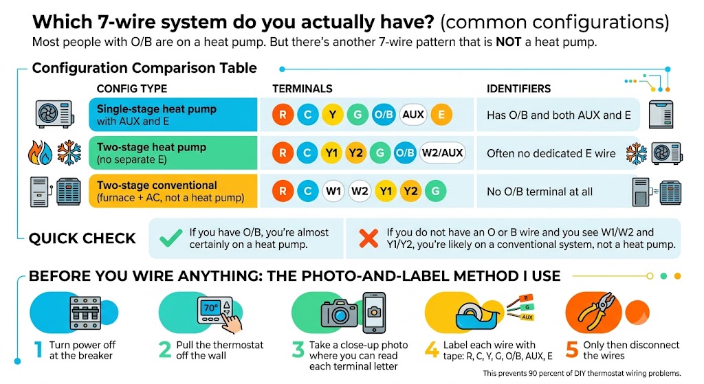
Most people with O/B are on a heat pump. But there’s another 7-wire pattern that is NOT a heat pump.
Configuration comparison table
| Single-stage heat pump with AUX and E | R, C, Y, G, O/B, AUX, E | Has O/B and both AUX and E |
| Two-stage heat pump (no separate E) | R, C, Y1, Y2, G, O/B, W2/AUX | Often no dedicated E wire |
| Two-stage conventional (furnace + AC, not a heat pump) | R, C, W1, W2, Y1, Y2, G | No O/B terminal at all |
My quick check:
- If you do not have an O or B wire and you see W1/W2 and Y1/Y2, you’re likely on a conventional system, not a heat pump.
- If you have O/B, you’re almost certainly on a heat pump.
Before you wire anything: the photo-and-label method I use
This prevents 90 percent of DIY thermostat wiring problems.
- Turn power off at the breaker.
- Pull the thermostat off the wall.
- Take a close-up photo where you can read each terminal letter.
- Label each wire with tape: R, C, Y, G, O/B, AUX, E.
- Only then disconnect the wires.
Step-by-step: How to wire a 7-wire Honeywell thermostat (the clean way)
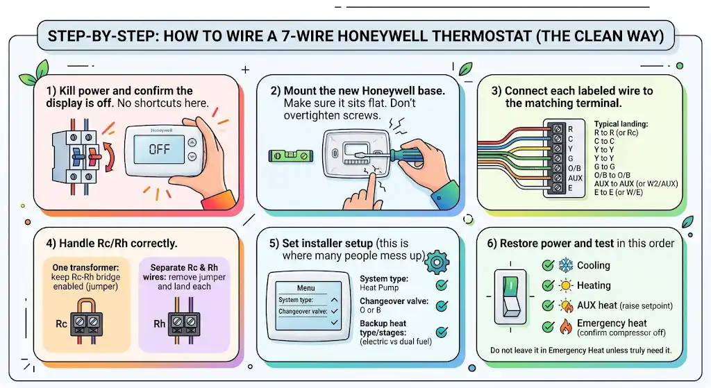
1) Kill power and confirm the display is off
No shortcuts here.
2) Mount the new Honeywell base
Make sure it sits flat. Don’t overtighten screws and crack drywall.
3) Connect each labeled wire to the matching terminal
Typical landing:
- R to R (or Rc)
- C to C
- Y to Y
- G to G
- O/B to O/B
- AUX to AUX (or W2/AUX depending on model)
- E to E (or W/E depending on model)
4) Handle Rc/Rh correctly
- One transformer and one R wire: keep the Rc-Rh bridge enabled (jumper or internal bridge depending on thermostat model).
- Separate Rc and Rh wires: remove jumper/disable bridge and land each wire separately.
5) Set installer setup (this is where many people mess up)
In the Honeywell installer menu, verify:
- System type: Heat Pump
- Changeover valve: O or B
- Backup heat type/stages: set correctly (electric vs dual fuel matters)
6) Restore power and test in this order
- Cooling mode: does outdoor unit run and indoor fan run?
- Heating mode: does it heat correctly?
- AUX heat: raise the setpoint to trigger AUX (if allowed by settings).
- Emergency heat: enable briefly and confirm compressor stays off.
Do not leave it in Emergency Heat unless you truly need it.
Quick diagnostic: is your problem the thermostat or the equipment?
This is a technician trick to isolate the thermostat from the system.
At the air handler control board (not at the thermostat):
- With power off, you can temporarily jump R to Y and R to G to see if the outdoor unit and blower run.
If it runs when jumped:
- equipment is likely fine
- thermostat or thermostat wiring is likely the issue
If nothing runs:
- you likely have an equipment-side issue (board fuse, transformer, safety switch, etc.)
Troubleshooting: common 7-wire Honeywell heat pump problems
| System heats when set to cool (or cools when set to heat) | O/B setting wrong in installer menu | Set changeover to O or B to match your brand |
| AUX heat runs too often | Thermostat settings, sensor issue, or low balance point | Verify system type, staging, and outdoor temp settings |
| No heat, compressor never comes on | Y wire loose, safety lockout, blown low-voltage fuse | Check 3A/5A board fuse, verify 24V R to C |
| Emergency heat does nothing | E not connected at air handler, or wrong terminal | Trace E wire at control board |
| Thermostat keeps rebooting | Weak or missing C wire | Measure voltage R to C under load |
| Fan runs but no heating/cooling | Y not connected, outdoor unit not powered | Check disconnect/breaker and Y circuit |
Brand tip: is your reversing valve “O” or “B”?
Most systems are O (energized in cooling). A handful are B (energized in heating). If you’re unsure:
- check the air handler wiring diagram sticker
- check the outdoor unit manual
- check the old thermostat installer settings if you still have access
In my experience, the most common “B” brands you’ll run into are Rheem and Ruud. But don’t rely on brand guesses alone if you can verify from the equipment label.
FAQ
What do the 7 wires on a Honeywell thermostat mean?
Most commonly, 7 wires mean a heat pump with both auxiliary and emergency heat:
R power
C common
Y compressor
G fan
O/B reversing valve
AUX automatic backup heat
E emergency heat (manual backup)
What is the difference between AUX and E on a Honeywell thermostat?
AUX is automatic backup heat that can run with the compressor.
E is emergency heat you manually select. It should lock out the compressor and run backup heat only.
If you run Emergency Heat all winter, your power bill will usually tell you pretty quickly.
Do I need both O and B wires?
No. You typically have one wire on the O/B terminal. You set O or B behavior in the thermostat’s installer settings.
Do Honeywell thermostats wire differently than Nest or ecobee?
The terminal meanings are basically universal across brands:
R, C, Y, G, O/B, AUX, E mean the same things.
What changes is how the thermostat handles:
Rc/Rh bridging
setup menus for heat pump and reversing valve
whether a C wire is required (many smart thermostats strongly prefer it)
Can I wire a 7-wire Honeywell thermostat myself?
If you’re only working with the low-voltage thermostat wires and you shut power off first, many homeowners can handle it.
Stop and call a pro if:
you find line-voltage wiring (120/240V)
you’re dealing with gas furnace internals beyond the control board
wiring at the air handler doesn’t match any standard terminals
you’re not sure whether you have a heat pump or conventional system
My “know when to stop” checklist
Call an HVAC technician or electrician if you run into any of these:
- Thick high-voltage wires and wire nuts at the thermostat location (that is not a standard HVAC thermostat circuit)
- Burn marks on the control board or repeatedly blown fuses
- You can’t identify the system type (heat pump vs conventional)
- You don’t have stable 24V between R and C
A wrong connection can blow a transformer or board. I’ve replaced plenty that could’ve been avoided.